| High Power Motor Driver 18V 15A Part# 0-PL755 |
Stock
Status: In Stock |
|
$39.99 |
|
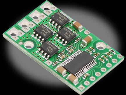
The High Power Motor Driver is a discrete MOSFET H-bridge designed to drive large DC brushed motors. The H-bridge is made up of one N-channel MOSFET per leg, and most of the board’s performance is determined by these MOSFETs (the rest of the board contains the circuitry to take user inputs and control the MOSFETs). The MOSFETs have an absolute maximum voltage rating of 30V, and higher voltages can permanently destroy the motor driver. Under normal operating conditions, ripple voltage on the supply line can raise the maximum voltage to more than the average or intended voltage, so a safe maximum voltage is approximately 24V. Note: Battery voltages can be much higher than nominal voltages when they are charged, so the maximum battery voltage we recommend is 36V unless appropriate measures are taken to limit the peak voltage. The versatility of this driver makes it suitable for a large range of currents and voltages: it can deliver up to 9A of continuous current with a board size of only 1.3 by 0.8in. and no required heat sink. With the addition of a heat sink, it can drive a motor with up to 12A of continuous current. The module offers a simple interface that requires as little as two I/O lines while allowing for both sign-magnitude and locked-antiphase operation. Integrated detection of various short-circuit conditions protects against common causes of catastrophic failure; however, please note that the board does not include reverse power protection or any over-current or over-temperature protection. Using the Motor Driver Warning: Take proper safety precautions when using high-power electronics. Make sure you know what you are doing when using high voltages or currents! In a typical configuration, only PWM and DIR are required. Note that the voltage on these inputs must be higher than 3.5V to be guaranteed to register as high, so we do not recommend connecting this device directly to a 3.3V controller. The two fault flag pins (FF1 and FF2) can be monitored to detect problems. The RESET pin, when held low, puts the driver into a low-power sleep mode and clears any latched fault flags. The V+ pin on the logic side of the board gives you access to monitor the motor’s power supply (it should not be used for high current). The board also provides a regulated 5V pin which can provide a few milliamps (this is typically insufficient for a whole control circuit but can be useful as a reference or for very low-power microcontrollers). Included Hardware Motor Control Options In locked-antiphase operation, a low duty cycle drives the motor in one direction, and a high duty cycle drives the motor in the other direction; a 50% duty cycle turns the motor off. A successful locked-antiphase implementation depends on the motor inductance and switching frequency smoothing out the current (e.g. making the current zero in the 50% duty cycle case), so a high PWM frequency might be required. |
|